Oscilloscope circuit A pc and an arduino: here’s your diy oscilloscope Circuit diagram oscilloscope sensor mos family seekic
Basic Oscilloscope Operation Worksheet - AC Electric Circuits
Oscilloscope eddy bergman ne555 An electronic device circuit diagram with the scr and other components Oscilloscope math functions aid circuit analysis
Oscilloscope lcd circuit microcontroller
Oscilloscope basic operation ac circuit line worksheets worksheet circuits electric dc coupling screen setting allaboutcircuits waveform arduino electricity settings electronicOscilloscope functions edn Oscilloscope tv atmega32 avr circuit project atmel liquid interfacing displays crystal graphics using alsoOscilloscope arduino pc diy electronics open here bill materials projects.
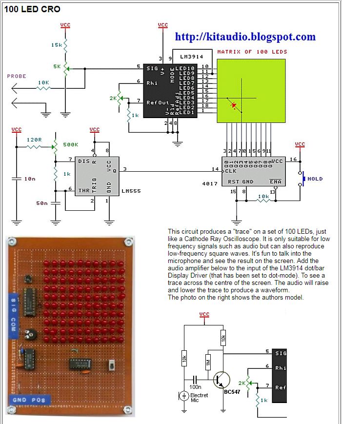
Led oscilloscope matrix educational pcb pcbway order here.: mini oscilloscope using lcd 128x64 & atmega32 Tv oscilloscope circuit with atmega8515 attiny12Basic oscilloscope operation worksheet.

Oscilloscope circuit with max492 pic16f877 graphic lcd
Using an oscilloscopeOscilloscope diagram block cro ray cathode internal circuit crt works digital using dc screen deflection electronics basics explanation outline shown Oscilloscope arduino channel using single making test circuits lcd homemade circuit output mode potentiometerEducational led matrix oscilloscope ~ simple projects.
Spectrum lcd oscilloscope analyzers circuit pic schematic diagram using microcontroller analyzer full circuits module gr fig shown nextLcd oscilloscope circuit project pic18f4520 Lcd oscilloscope circuit avr matrixsynth atmega32 project microcontroller cost bit nice very highOscilloscope pc circuit diagram based electronics computer electronic schematics board diy readymade dc project box input projects arduino iot circuits.

Lcd oscilloscope for spectrum analyzers using pic16f876a
Oscilloscope circuit analyzer usb schematics schematic input protocol adc comments circuitsEddy bergman.com: led oscilloscope with 100 leds. Arduino oscilloscope lcd diy using graphic oled electronics labDiy oscilloscope using arduino and graphic lcd (osciduino).
Atmega162 lcd oscilloscope circuitLcd oscilloscope circuit project pic18f4520 Mos image sensor oscilloscope circuit diagram 3 a familyTransformer isolation.
Oscilloscope schematic avr lcd circuit diagram diy schematics using circuits mini make features atmega32
Transformer isolation oscilloscope ground test isolated probe voltage point circuit grounded does electrical using resistance voltages grounding articles technical figMaking a single channel oscilloscope using arduino .
.


Making a Single Channel Oscilloscope using Arduino | Homemade Circuit

Oscilloscope circuit | All About Circuits
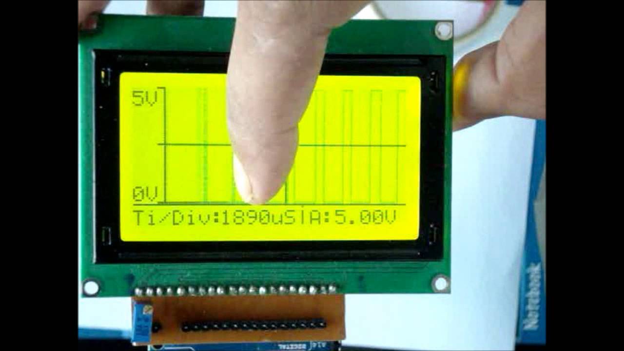
DIY Oscilloscope using Arduino and Graphic LCD (Osciduino) - YouTube

Basic Oscilloscope Operation Worksheet - AC Electric Circuits
.: Mini Oscilloscope using LCD 128x64 & ATMEGA32

LCD Oscilloscope for Spectrum Analyzers using PIC16F876A

OSCILLOSCOPE CIRCUIT WITH MAX492 PIC16F877 GRAPHIC LCD

TV OSCILLOSCOPE CIRCUIT WITH ATMEGA8515 ATTINY12
